2 Meter Full Wave Quad Loop
The Magic Wand Antenna
A Novel 2 Meter Full Wave Quad LoopBy
WB5ISMJERRY RANDALL (SK March 12, 2011 - See update below)
A Novel 2 Meter Full Wave Quad LoopBy
WB5ISMJERRY RANDALL (SK March 12, 2011 - See update below)
DON'T LAUGH about this antenna! Ripley says "Believe it or Not"!
The idea for this 2 meter full wave loop antenna came from QST., February, 1973.
The design from QST was altered to eliminate instability in matching to a 50 ohm transmission line. The method used to obtain this new design was strictly through experimentation.
Below is a trial by jury! We present the evidence!
Below is a trial by jury! We present the evidence!

Description:
The antenna is basically a quad, 1 full wavelength at 2 meters. Part of a wavelength on top and part on the bottom in the form of two loops connected together. The feed point is in the vertical plane of the antenna between the loops so it's basic polarization would be vertical.
There are some horizontal characteristics common to all quad type antennas.
This antenna is omni-directional but, it does have some directive characteristics. They are no more than that experienced when using a vertical mobile antenna that uses the car body for it's ground plane.
This is a plus for this antenna because it does not require a ground plane for resonance.
Field strength measurements show that the new design is equal in performance to a 5/8 wave vertical in all cases, plus in the directive lobes, there is about 2 field strength units gain over the 5/8 wavelength vertical!
There is one other plus for the design, the noise factor is considerably less than the 5/8 wave vertical antenna.
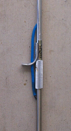
Construction: See pictures and drawings for more detail and note that instructions follow for mounting on top of a Newtronics Hustler MO 2 foldover mast for mobile use.
The antenna consists of 2 each, 8 inch square loops, one above the other separated by 16 inches from the top of the top loop to the bottom loop.

A bird's eye view would show a square (bottom loop) bisected by the top loop. See drawing below:
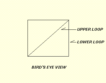
In the drawing above, the top loop is shown going from one corner to the other. This is only drawn this way to show the bisecting direction of the top loop. It does not go all the way across from corner to corner. The antenna conductor about 83 - 84 inches long, is constructed from # 9 half hard aluminum wire and all dimensions are from CENTER TO CENTER in pictures and sketches on this page.
The two adjacent vertical sections between the top and bottom sections of the antenna MUST be insulated from each other. NO MORE THAN 1/4 INCH spacing between the vertical sections. The insulation can be a piece of RG58 outer covering that is slipped over one of the vertical sections or you can use insulated wire, shrink tubing, etc.
Please note that the aluminum wire used in the pictures already has an insulating coating. At the feed point adjustment in picture below, you can see where it has been removed.
The feed point is arranged in a manner whereby the center conductor and shield conductor from the 50 ohm feed line is attached to a short "stub" for tuning purposes. Note in the drawing above that the feed point is off center in the vertical section.....not centered.

FEED POINT CLOSEUP
Electrically, the center conductor of the feed line attaches to the upper portion of the vertical section point on the stub leading to the top loop and the shield attaches to the lower vertical section stub leading to the bottom loop.
The short tuning stub, one side to the top vertical section, and the other side to the bottom vertical section is approximately 5 inches long at the long side, separated by 2 inches from the bottom side and is used to slid the center conductor and the shield connection of the feed line along it's length for tuning the antenna.
The SO 239 is slightly off center looking at it from the bottom loop and the coax feed can be brought down thru the bottom loop. This of course would have to be done before any SWR adjustment.
In the closeup above, 1/4 inch copper tubing has been attached to the center pin of the SO-239 connector and then to the upper section of the stub. Another right angle section was flattened on the end, drilled for a brad and was attached to the lower stub section. A small bolt, lock washer and nut could also be used instead of a brad.
The ends of the tubing have been drilled out so the # 9 aluminum wire can slide through it. Then the ends of the tubing are tapped to accept an Allen type set screw.
The end result of this method is to make it easy to adjust the length for tuning so as to either lengthen or shorten the total length of the aluminum loop which should be around 83 - 84 inches end to end including tuning stub.
There are several methods to make the tuning section adjustable and depending on your construction techniques and material on hand, you can use your imagination in connecting the feed line to the stub after final adjustments.
One simple method would be just to temporarily twist the center conductor and shield of the feed line tightly to the respective upper and lower portions of the stub, test SWR using low power, adjust length as needed, repeat as necessary for lowest SWR. Mark the final attachment points on the stub and then using whatever method you choose, attach feed line to stub at these points eliminating the SO 239/copper tubing arrangement. # 9 wire Butt connectors can be used to crimp the coax center and shield wire to the end of it's respective stub at the lowest SWR points.
ADDITIONAL NOTES:
ADDITIONAL NOTES:
# 9 aluminum wire may be difficult for you to locate. Simply substitute #10 or experiment with wire sizes. The feed point section can also be arranged on the opposite side of the vertical section rather than towards the center of the loops as in pictures above. There should be no difference in performance. This will allow the connection of the feed line to the "outside" corner rather than the center portion of the antenna. Strictly your choice.
Please note that copper wire, tubing, etc and the aluminum wire will eventually react with oxygen and corrode due to dissimilar metals touching.
You should seal all connections with some type of Silicone sealer to help prevent this reaction. Seal end of coax and Allen head screws also to prevent water from wicking inside and ruining your connections and coax.
The antenna can be used inside the house by suspending it with cord, heavy string, etc from the ceiling or attach it to a wall stud, the higher off the ground the better the performance. The 2 meter full wave loop is so light, it can even be attached to most any non-conductive support with good tape. Keep it away from any large metal surface closer than about 1 wavelength. The farther away, the better. It can also be used as an indoor attic emergency backup antenna after a suitable location and mounting is found. Remember to keep it as far away as possible from air conditioning duct work, pipes, electrical and telephone wires, catv cables, etc.
Additional non-conductive support such as PVC pipe can be added from the top loop to the bottom section for added support if used outdoors or mobile. In the picture above, Jerry used nylon wire ties and heat shrink for better stability.
Heavy Duty Mobile Mounting Using Hustler Mast:
Heavy Duty Mobile Mounting Using Hustler Mast:
A good sturdy and stable method of using the antenna mobile is to mount it on top of a Newtronics Hustler MO 2 breakover mast.
See pictures and description below.
See pictures and description below.

Full Length View of Modified Hustler Mast Above

Center View at Fold Over Antenna Attachment End
PL 259 End (Top of Hustler Mast) General instructions and modification for using a Hustler mast
with the Magic Wand antenna:
The Hustler mast is about 54 inches long and is designed to fold over in the middle. It is a Model MO 2. The intent of the basic modification of the original mast is to allow a PL 259 connector along with it's coax leading to the radio to be attached to and supported directly by the mast and connected directly to the SO 239 at the feed point of the antenna for better support of the entire antenna while operating mobile.An appropriate length of low loss coax, (50 ohm), with about 1 foot extra on each end is fed into holes drilled near the base of the mast, at the bottom and top section of the break point and then up and out the top of the mast. The two holes at the break over point can be eliminated if you have no need to fold over the mast. This would make the modification of the mast more simple and make the feeding of the coax into and out of the holes much easier without using a "pull wire", kinda like using a coat hanger for fishing coax thru a whole in a wall. Also, you may desire to use one long length without any connectors at the base of the antenna as pictured, running from the radio to the top of the mast. Be sure to add about 1 foot of coax out of the top in either case. Now pull the coax back down into the top section so it will be out of the way for the next step.
Now take a PL 259 un-connected at this time and follow the instructions below:
The inside diameter of the top of the mast and the outside diameter of the PL 259 reducer for the coax connector may have to be slightly ground down or filed for a tight fit of the PL 259 on top of the mast for proper alignment. Your PL 259 probally won't go into the mast. Just grind or file the outside diameter of the reducer (area surrounded by red dot in picture below) so you can push it down into the mast. When you have a good snug fit, remove it, and judge or measure exactly the center of the outer edge of the reducer between the coax and the main shell of the connector.
See picture below:
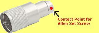
This distance should be marked on the outer surface of the mast for drilling a small hole on each side of the mast that can be tapped for Allen type screws. Remember that the Allen set screw has to go thru the outside mast to make good solid contact with the reducer. Doing this with Allen set screws make for good mechanical strengthening at this point on the mast. This will be the point on the mast with strain under wind load. You may chose to use another method that works better for your purpose and mechanical experience. Regardless of what method you use, don't drill into the coax!
When you have completed the pre-installation of the PL 259 and are satisfied with the way it attaches to the mast, you can then push the coax up and out of the top and then simply attached the end of the coax to the PL 259 using solder as usual and push it firmly down onto the mast. Tighten with the Allen set screws firmly!
Attach final assembly to the mount on your vehicle, check and adjust SWR and have some fun with the WB5ISM 2 Meter Magic Wand antenna!
73 Jerry WB5ISM
73 Jerry WB5ISM
Editors note:
I must admit, when Jerry brought a sample of this antenna to the QTH for a photo session, (the antenna), and trial by jury from me, (again, the antenna), I was certainly surprised at it's size or I should say the lack of size. This antenna is TINY as can be seen in the full length picture with the tape measure showing 8 inches! It can't weigh more than a few ounces! The full wave loop antenna is based on the tried and true formula for a loop, 1005 / freq in mhz = length. Design it for the bottom end of the band so you will have some room to play with the tuning. It's always better to have it too long rather than too short when it comes to any trimming or changes.
Although Jerry's original article had slightly different measurements than in this article concerning the spacing between the feed stub and the loops, the actual measurements taken directly from the sample antenna appear here below.
TRIAL BY JURY!
The trial by jury was performed by attaching the antenna to a wooden yard stickinside the shack to a plastic filing cabinet which made the top of the antenna about 5 feet off the floor (1st story on concrete foundation) and adding a few feet of RG 58 to it complete with connectors on each end. I did not use the Hustler mast.
Low power (15) watts was used to check that the SWR was not too high at the center of the 2 meter band.
Low power (15) watts was used to check that the SWR was not too high at the center of the 2 meter band.
Without any tuning I was able to hit repeaters 70 to 80 miles away using 50 watts with an average S7 to S9 signal from the repeaters! No trouble to get full scale S meter readings from the closer machines. Keep in mind that the area I live in is surrounded by flat terrain to very low rolling hills and some of the repeaters are located well above average terrain but some are not.
I'll repeat again, the antenna is TINY AND VERY LIGHT which in my opinion may be another plus for it! There should be very little wind resistance if it were to be used mobile. It is not a heavy duty antenna due to the small diameter # 9 aluminum used for the full wave loop, but upon talking to Jerry first hand, neither of us could see why larger diameter solid wire or tubing could not be used. Of course, unless some method of supporting the loops is used, then the larger the tubing, the more difficult it will be to keep it up!
VERDICT! GUILTY........BUILD IT FOR SOME REAL 2 METER Tiny Antenna FUN!
NO! It's not a full blown pair of stacked 13 element yagis and was not intended to be but it's performance certainly out does it's size!
I did not check the bandwidth of the antenna, (see updates below), but it certainly, in my opinion, performed well in this limited, non-scientific test from INSIDE the QTH all across the 2 meter band in the FM repeater portion!
Just think how it should perform higher up from the court room floor away from the judge! (I did not have coax long enough during the test to get it outside and higher)
Update: OUTDOOR TESTING! After finding some RG 58 that had been hiding from me and adding a PL259 to one end, I had just enough to install the antenna outside the house and away from any metal objects.
I only had enough coax to install the full wave loop about 6 feet from the top of the top loop to ground level on some PVC pipe. It was simply tied to the pipe with string.
I only had enough coax to install the full wave loop about 6 feet from the top of the top loop to ground level on some PVC pipe. It was simply tied to the pipe with string.
I used an MFJ-259B to check the SWR and found that it had changed considerably from the indoor test. After a bit of adjustment of the feed point by moving it closer to the vertical sections using Jerry's Allen screw setup, I was able to get the following readings on the MFJ 259B:
Freq SWR
144mhz 1.9 to 1
145mhz 1.5 to 1
146.06mhz 1.2 to 1
146.38mhz 1.2 to 1
147mhz 1.4 to 1
148mhz 1.8 to 1
144mhz 1.9 to 1
145mhz 1.5 to 1
146.06mhz 1.2 to 1
146.38mhz 1.2 to 1
147mhz 1.4 to 1
148mhz 1.8 to 1
The lowest SWR point was just about centered on 146mhz giving a 320khz spread without change according to the MFJ test and assuming it is accurate. A random length of coax was used for the tests. These same SWR tests were repeated a few days later with another copy of the Full Wave Magic Wand antenna attached to the Hustler mast on top of a 10 foot section of PVC pipe making the antenna about 14 feet in the air with identical results as before.
During these outdoor tests, the Full Wave Loop was compared to a Slim Jimmounted above it at about 18 feet in the air to it's top. The Slim Jim is about 5 feet long tip to tip. Yes, I know that this is not a fair test, but sometimes you have to do the best with what you have.
VERY STRANGE RESULTS!
On the air testing comparing the Full Wave loop at about 6 feet to it's top with the Slim Jim at about 18 feet to it's top revealed these S meter readings:
Frequency Slim Jim Full Wave Loop
145.29 S5 S1
147.060 Full Scale S9
147.080 S9 S9146.700 Full Scale S9
145.410 S7 S1
146.880 S9 S5
147.260 Full Scale S7
147.000 S5 S5
146.800 S7 S7
145.310 Full Scale S9
145.29 S5 S1
147.060 Full Scale S9
147.080 S9 S9146.700 Full Scale S9
145.410 S7 S1
146.880 S9 S5
147.260 Full Scale S7
147.000 S5 S5
146.800 S7 S7
145.310 Full Scale S9
Note that at the frequencies marked in red above that the S meter readings are equal...........VERY STRANGE. To determine if the Full Wave loop had any directional properties, it was rotated 90 degrees and using the known direction of certain repeaters in the area, the S meter tests were performed again. The results were that I could not detect any difference in directional patterns using the S meter readings by rotating the loop.
Bottom line:
The Slim Jim did out perform the Magic Wand and it should have, but as stated earlier....this is not a fair test. The Slim Jim was 3 times higher above ground, about 5 feet tall which is about 3 1/2 times as long vertically and has some gain due to it's low angle of radiation! Kinda like comparing an ant with an elephant!
Taking into account that the Slim Jim was about 3 times higher and is reported to have a very low angle of radiation (8 degrees), I would say that this 2 meter Full Wave Loop, the Magic Wand antenna by WB5ISM really showed it's stuff in this very limited non-scientific but real life test!......my personal overall rating of this antenna would have to be a 5 STAR performer for such a TINY criminal with a big mouth!
Thanks to Jerry, WB5ISM for sharing his experimentation with us and his design of the 2 Meter Magic Wand Full Wave Loop! Fantastic job Jerry!
73 N4UJW (The Judge and Jury in this crime against BIG antennas)
source: http://www.hamuniverse.com/2meterfullwaveloop.html
source: http://www.hamuniverse.com/2meterfullwaveloop.html


selamat malam pak andy saya memiliki rockwell collins kwm 380 yang ingin saya servis, jika bapak bisa mohon hubungi saya di dimasmartokoesoemo@gmail.com
BalasHapusselamat malam om Dimas !
BalasHapusok saya email ke alamat email diatas ya
terima kasih